What
is CAD?
 |
| Computer Graphics |
The field of computer graphics has its beginnings
back in the early 1960s with the work of Ivan Sutherland who demonstrated
a sketching program called Sketchpad in 1963. Sketchpad allowed
engineers for the first time to generate drawings by using an interactive
graphics terminal, and to manipulate them by using a light pen and keyboard.
From these beginnings, the field developed rapidly.
The first CAD systems appeared in the mid-1960s—e.g., IBM's DAC-1 for
use by General Motors in car design. A characteristic of the early years
of CAD was that architectural uses of CAD lagged behind engineering applications.
This was due, in part, to economic considerations—CAD typically required
investments of hundreds of thousands of dollars.
The introduction of personal computers, particularly the IBM PC in 1981
was a watershed for architectural CAD. In 1982, a company called Autodesk
introduced the first CAD program for the IBM PC, called AutoCAD.
With this, CAD became truly affordable.
Computer graphics is a hybrid field. It comprises the art and science
of creating images of three-dimensional objects. It brings together computer
programming, descriptive and analytical geometry, linear algebra, traditional
art, and traditional presentation techniques.
Computer graphics means different things to people from different disciplines.
However, in architecture (as well as engineering and manufacturing), it
brought with it computer-aided design (CAD), a new electronically-based
medium for creating drawings and images of envisioned designs. For architects,
CAD changed the way they worked—drafting tables and pencils were replaced
by computer workstations and CAD software. |
| Nuts and Bolts
(i) Hardware |
Computer drawings and images are created using computer
hardware and software.
The computer hardware of a typical CAD workstation consists of:
-
input – keyboard, mouse, etc.
-
processing – done by a processor chip (or multiple chips) known as the
Central processing Unit (or CPU); by fast working memory called Random
Access Memory (or RAM), used to store information temporarily for the CPU;
large-capacity hard disks used to more "permanently" store data; and other
devices (e.g., graphics accelerator, network, etc.).
-
output devices – used to display the graphic information after it is processed
by the CPU. Examples are monitor, printer, etc.
|
| (ii) Software |
The computer system relies on an operating system
(e.g. Microsoft Windows) to do its job. Through a graphical user interface
(GUI) users interact with the system by issuing commands. CAD applications
(e.g. AutoCAD) are used to create drawings and models. The user interface
typically consists of icon toolbars, pull-down menus, and graphics and
command windows. To draw a line, for example, the user can point and click
on the appropriate icon  ,
choose an item from a pull-down menu, or enter Line in the Command
entry window (see AutoCAD Basics tutorial). Once the command is
issued, the system will request that additionl information be provided,
such as the location of the line's endpoints. The user then points and
clicks at appropriate locations in the graphics window to specify points,
or enter co-ordinates via the keyboard. ,
choose an item from a pull-down menu, or enter Line in the Command
entry window (see AutoCAD Basics tutorial). Once the command is
issued, the system will request that additionl information be provided,
such as the location of the line's endpoints. The user then points and
clicks at appropriate locations in the graphics window to specify points,
or enter co-ordinates via the keyboard.
A line is described in CAD by its endpoints' co-ordinates. For each
line in the drawing, CAD software stores a database record that
describes its properties, such as endpoint co-ordinates, colour, and thickness.
To create an image within the graphics window, the CAD software reads the
database records and draws each object by converting its 3D co-ordinates
into 2D co-ordinates of the screen.
Extruding or revolving 2D shapes produces 3D objects—e.g., to
extrude a 2D shape, the user first selects the appropriate tool, then selects
the shape to be extruded, and specifies the height of extrusion. Various
3D objects are available as "primitives" (i.e., predefined in software
ready to be placed anywhere in the modelspace). The 3D objects can also
be manipulated (moved, rotated, scaled, stretched, intersected, etc.).
Usually, by default, the 3D objects will be shown in wireframe mode.
The user, however, can create hidden-line views of their work (HIDE
command in AutoCAD). Shaded views may also be generated.
Most modern CAD packages support rendering—an image of the 3D
model showing simulated illumination and surface effects such as transperancy,
reflection, and shadows. Light emitting objects, such as the Sun or a spotlight
for example, can be located in 3D space. Material definitions can be attached
to 3D objects to make them more realistic. The rendering software will
compute an image based on the model's:
-
geometry,
-
lighting, and
-
surface material information
by taking into account factors such as:
-
angle and intensity of light incident on the surface,
-
degree to which the surface reflects and transmits the light incident on
it.
Finally, the produced drawings and images can be printed on paper. Computer-controlled
milling machines can use the model data to manufacture components if required. |
| |
|
2D
Drawing
|
| Graphic Objects |
In many ways, computer-aided drafting (CAD) is analogous
to traditional, or manual, drafting. In manual drafting, a draftsman generates
graphic objects using tools such as a ruler for straight lines. In CAD
systems, the draftsman, or the "user", uses various tools to draw. These
tools are usually represented in CAD programs as icons that are grouped
together in toolbars that float above the drawing window on the computer
display (see AutoCAD Basics). And, as in manual drafting, these
tools indicate what can be drawn—straight lines are drawn with a "line"
tool, for example.
However, this is where the analogies end: in manual drafting, the draftsman
draws a line by moving a drawing implement between two points, depositing
ink along the way; in CAD, the user indicates the start and end points
with the CAD program doing the rest.
As well as providing tools to draw straight lines, CAD programs also
offer tools to draw circular arcs, ellipses, circles, rectangles, squares,
and polygons. Many CAD systems also offer spline curves and polylines:
-
spline curves are specified by control points—i.e., points that determine
and control curvature by being pulled into position.
-
polylines are connected chains of lines and arc segments that are treated
as single objects and that may form open or closed shapes.
In CAD, each graphic object may be assigned attributes such as colour,
line type, etc. |
| 2D Co-ordinate
Systems |
In CAD systems, the user draws on a two-dimensional surface
of infinite size, which has its origin and two axes (x and y) perpendicular
to each other, which are used to determine the location of points relative
to the origin. This is called a 2D Cartesian co-ordinate system, and is
fundamental to all 2D CAD systems. Under a cartesian system, points are
positioned in cartesian space by their x and y co-ordinates. All graphic
objects are drawn by specifying point locations within this rectangular
co-ordinate system.
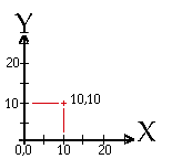
Examine the figure below. The co-ordinates of the point shown is (10,
10).
Many CAD systems also provide point specification using polar co-ordinates—i.e.,
point location is described by its distance from the origin and an angle
that the connecting line forms with the x axis. |
| CAD Drawing Aids |
In addition to entering points numerically, users can also
indicate point locations graphically by directly picking points in the
drawing display area. Most CAD systems use a cursor (usually a pair
of cross hairs) as a visual aid for point selection. The location of the
cursor is controlled by a pointing device (usually a mouse or stylus on
tablet). The act of picking a point (usually by clicking a mouse button)
is referred to as "digitising". |
| (i) Rubber-banding |
"Rubber-banding" is another visual aid in CAD. Typically,
when drawing a line, after the first point is picked, the system will display
a "rubber-band" line that will dynamically follow the cursor until the
second point is clicked. |
| (ii) Grids |
CAD systems also feature grids, regular patterns of dots
displayed across the drawing surface. Grids are also used in manual drafting
but there they are fixed—they cannot be changed as needed during drawing. |
| (iii) Snaps |
Drawing with the aid of grids, however, is imprecise—choosing
grid points precisely is not easy. To remedy this, CAD systems provide
the snap feature. Snap forces the cursor to jump in exact intervals
on top of an invisible grid of points. A user may specify different intervals
for grid and snap—e.g., a grid interval may be set to 1 metre and the snap
to 1 centimetre. |
| (iv) Object snapping |
New objects can be drawn by object snapping, that
is, by precisely selecting significant points on existing objects: endpoints
or midpoints of lines, etc. |
| (v) Construction
lines |
Construction lines—temporary lines that the user can snap
to in drawing the model—also offer time-saving benefits. When the construction
lines are no longer needed they are usually deleted or their layer made
invisible ("switched off"). |
| Basic Editing |
CAD drawing objects can be inserted, selected, and, once
selected, can be deleted, transformed, or duplicated. Objects are inserted
by selecting the appropriate drawing tool, such as line, arc, etc.,
and by locating points that define the object to be drawn, such as endpoints
of a line.
An object must be selected before it can be deleted, duplicated,
or transformed. Object selection is one of the most basic of CAD operations.
It can be performed:
-
one by one, or
-
as a group by specifying a selection boundary (usually a rectangle) and
choosing objects that are within, crossing, or outside the specified boundary.
Deletion of objects is performed by removing the corresponding records
from the drawing database. In addition to deletion, the basic transformations
of translation, rotation, reflection, and scaling
should also be offered by the CAD system.
As well as these operations which don't alter the geometry of selected
objects, there are some that do. To lengthen a line or displace a corner
of a rectangle, a user can choose a specific point (a grip in AutoCAD)
and drag it to a new location. A user can also break, trim,extend,fillet,chamfer,
or
stretch
existing objects.
Existing graphic objects can be duplicated using copy, array,
and offset operations. Copy is used to create exact duplicates of
existing objects. Array duplication creates circular or rectangular patterns
of selected objects. Offset creates, at a specified distance, a new object
similar in shape to the original one. |
| Viewing in CAD

|
Unlike manual drafting, there is no need in CAD to determine
in advance the sheet size and scale. There is NO drawing scale: ALL
sizes and distances are specified using their full-scale values—a
10 metre wall is drawn as a 10 metre long wall-shaped object. It is only
at the printing stage that drawing size needs to be determined based on
sheet size.
How then can a computer display of small and finite size contain a model
with potentially almost infinite extent? Zooming facilitates viewing
operations: the user zooms in to view more detail, and zooms out to view
a wider extent.
Another important viewing operation in CAD is panning. To see
another portion of the drawing without changing the display scale, a user
pans to it by "moving" a rectangular display window until it's over the
desired spot. |
| Boundaries/Limits |
Most CAD systems require that boundaries or limits of the
drawing area be specified to facilitate internal computation. This is a
potential source of confusion for new users who are told that, in CAD,
specifying drawing sizes and scales is not required.
Possibly to prevent such confusion AutoCAD provides a drawing setup
wizard through which users can specify a desired drawing "size" and "scale".
The specified values are used to determine the drawing boundaries (limits). |
| Layering in CAD |
In manual drafting, different building systems, such as
wiring and air conditioning, are often drawn on separate transparant sheets
of paper, which are often overlaid on one another to produce final drawings.
In these drawings, symbols are used to denote components such as switchboards,
air conditioning units, etc.
CAD systems use analogous concepts to structure drawings. Instead of
transperant sheets, CAD systems use layers, named parts of a drawing
with similar content. A single drawing can contain many layers. For example,
graphic objects representing wall elements of the first floor can be assigned
to a layer named 1-WALLS, whereby the "1" denotes the first floor, and
"WALLS" describes the content.
Layers thus facilitate the organisation and display of graphic information.
Whether or not specific layers are displayed depends on what information
is needed. If a user wishes to work on the HVAC system then layers such
as FURNITURE can be "switched off". AutoCAD provides a virtually unlimited
number of layers.
Apart from layers, a drawing can also be structured by grouping objects
into hierarchies and by using external references. External references
are useful for complex drawings where small size is important. |
| Symbols |
Symbols are repeatable shapes that provide another way
to structure drawings. In AutoCAD they are known as blocks. Creating
blocks is rather akin to stencilling: to define a symbol, a designer first
creates its master definition that contains graphic objects and a reference
point that is used to place instances of the symbol. Unlike stencilling,
however, symbols defined in CAD can have different scales. |
Hardcopies  |
As discussed above, CAD drawings are created using full-scale
values for co-ordinates and dimensions; paper size and drawing scale are
only specified when printing or plotting. |
| Planning Drawings |
Before a line is drawn on the screen, the drawing should
be set up. In order, the steps are:
-
indicate the units to be used—English or metric.
-
choose units display format—engineering, architectural, etc.
-
drawing limits should be specified taking into account the building's full-scale
size.
-
decide drawing layers (additional layers can be added later if need be).
-
decide appropriate grid module needed for visual reference, e.g., a 1 metre
by 1 metre grid.
-
select snap module for accurate drawing.
After the initial setup, a framework or construction or gridlines is typically
drawn as a visual guide to drawing.The skeleton lines can be used to snap
new graphic objects quickly into place.
When it comes to entering an existing non-digitised drawing into a CAD
system four methods are available to enter the drawing information:
-
tracing – using a tablet or digitiser to trace drawn objects;
-
scaling – involves the reading of dimensions by using a scale rule;
-
scanning – using a device to turn the drawing into a digital image and
then into a CAD drawing via conversion software; and
-
hybrid scanning – the scanned image is used as an underlay in the CAD software,
and graphic objects are drawn on top of the scanned image.
|
| |
Getting
Started
|
| Hardware

|
Students taking this subject may use the Digital
Celebris GL Pentium Pro PCs located in the level 2 Computing Lab (room
287). Each of these machines is essentially the same with a Pentium Pro
200 MHz CPU, a 17" high resolution colour graphics monitor, 64 MB of RAM
and a mouse pointing device. Some of the PCs (and Macs) are equipped with
Zip
drives for archiving files. |
| Software |
This tutorial is based on Release 14 of AutoCAD running
on a Windows 95/NT PC. |
| File storage |
All students having accounts on the Faculty of Architecture
server are each allocated 25 MB of space in their home directories. These
home directories may be accessed from any computer (PC, Mac, or Unix) on
the local network and on the internet. Opening your AutoCAD drawing files,
naturally, requires the use of AutoCAD R14 or any other CAD program capable
of opening DWG files (e.g. ArchiCAD). |
| Logging-on |
Log-in on one of the Faculty PCs by entering your loginID
and password (if you haven't been issued with one see a member of the teaching
staff). If this is the first time you have logged-in on one of the lab
PCs then you will first need to register—do so by clicking on the Register
button first. |
| Warning about Disk
Quotas |
All user accounts on the Faculty computing system have
a disk space quota allocated to them. For student accounts this quota is
usually set at 25 MB (megabytes, or million bytes). As a user saves files
to their home directory on the Faculty server, space is consumed and the
quota limit is approached. Once the quota is reached, the server will
permit no further files to be stored there. The user will then be faced
with the decision of either deleting unwanted files or moving files off
the server on to removable media such as Zip discs (store about 100 MB)
or floppy discs (store about 1.4 MB).
AutoCAD is a disk space glutton—it creates all sorts of extraneous files
unbidden by the user, and every time you save a drawing file, it keeps
the previous version (filename.bak) in case you change your mind and want
the earlier version back.
Warning! – if you are close to exceeding your
disk quota, AutoCAD may stop working properly, or fail to start-up at all.
This is because it can't find the space to create the vital temporary files. |
|