Text
 |
| |
Text usually conveys important information in drawings.
Text is used for title blocks, to label parts of the
drawing, to give specifications, or to make annotations.
AutoCAD provides various ways to create text. The method you use
depends on the requirements of your drawing:
- For long, complex entries with internal fomatting, use
multiline text via the MTEXT command.
Multiline text:
- fits a specified width but can extend to an
indefinitelength.
- consists of any number of text lines or paragraphs that fit
within a width you specify. Regardless of the number of lines, each
set of paragraphs forms a single object, which you can move, rotate,
erase, copy, mirror, stretch, or scale.
- has more editing options than line text. You can apply
underlining, overlining, fonts, colour, and text height changes to
individual words or phrases within a paragraph.
- For short, simple entries that do not require internal formatting,
use line text using the DTEXT or TEXT command. Line text is
more convenient for labels.
Although all newly entered text uses the current text style
(see below: Working with Text Styles), which establishes the
default font and format settings, you can use several other methods to
customise the text appearance. You also can save collections of
formatting choices under style names for later use. |
Adding Line Text to a Drawing
|
| |
| |
The Line Text command allows you to enter one or more
single lines of text . Each line is treated as a separate object
that you can relocate, reformat, or otherwise modify.
To create line text:
Go to the menubar and choose Draw > Text >
Single Line Text
Command: _dtext Justify/Style/<Start point>:
With the mouse, indicate the insertion point for the first
character. If you press ENTER, AutoCAD locates the new text
immediately below the last text object you created, if any.
Height <0>: 500 (Specify the height of the text)
Rotation angle <0>:
by simply pressing , you are
accepting the offered value of 0 for the text angle .AutoCAD generally
offers "default" values for most requested input . The default value is
shown in angle brackets on the Command Line.
Text:Floor Plan
The Text: prompt indicates that you should enter the text that
you wish to appear on your drawing. An "I-beam" cursor will also appear
at your specified starting point. You can enter as many lines of text as
you wish, each terminated with . To
stop the process, simply press ENTER twice (the second time, at
the Text: prompt, effectively terminates the command). Try using
the Line Text command again (just by pressing ENTER to recall the
command), but this time, instead of typing the text height as a number,
use the mouse pointer to pick two points on the screen that "shows" the
text height that you want. In general, AutoCAD will always allow you to
"point" to a distance (by picking two points) just as it also lets you
type in a coordinate pair (x and y values) instead of picking a point on
the screen.
Move cursor vertically, up to a suitable distance below the long
elevation, pick a point and continue:
Text: Elevation A
Move cursor horizontally, across to a suitable distance below the
other elevation and continue:
Text: Elevation B (double
ENTER to quit command) |
| Working with Text Styles |
When you create text, AutoCAD uses the
current text style, which sets the font, size, angle, orientation,
and other text characteristics. When you create text, the defaults for
the current style are displayed at the prompts. You can use or modify
the default STANDARD style, load another style, or create a new style.
New text inherits height, width factor, obliquing angle, backwards,
upside-down, and vertical alignment properties from the current text
style. Except for the STANDARD style, you must create any text style
that you want to use. Use the Text Style dialog box to create or
modify text styles.
If you change an existing style's font or vertical alignment, ALL
text using that style is regenerated using the new font or orientation.
However, for text objects, changing other text style properties, such as
text height, does not change existing text.
|
| Creating text styles |
To create a text style, go to the menubar and select
Data > Text
Style. Use the Text Style dialog box that then appears
to configure a style. |
| Modifying text styles |
To modify a text style , bring up the
Text Style dialog box, as above, select a style name from the Styles
text box, and change any of the options as needed. |
Adding Multiline Text to a Drawing
|
| |
The following instructions demonstrate how text of a
particular font and style can be incorporated into a drawing, with the
aid of the Textstyle Dialog Box.
Command: Change layer to TEXT
Refer to earlier tutorials for method of changing layers.
Before you add the text, define a text style based on the
Times New Roman TrueType font. From the Format menu choose
Text Style.
Click New, and enter Times as the new style name. In
the Font Name drop-down list choose the Times New Roman
font. Click Close to continue. |
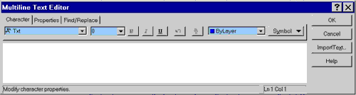
Text Tool |
Choose the Text tool on the Draw toolbar.
This command allows you to enter several lines of text inside
a dialogue box . AutoCAD will prompt you (on the Command Line) to pick
two points that form the opposite corners of a rectangle that defines
the area in which the text is to be positioned ... the Edit MText
dialog will then appear. Enter a few lines of text in the dialog box and
then click OK. Notice that the text wraps automatically in the dialog
box to fit within the width of the rectangle that you defined. You may
notice also that if there is too much text to fit in the rectangle, then
AutoCAD simply allows it to spill over the lower boundary of your
rectangle.
Once the text is on the drawing, it is treated as a single entity
by AutoCAD.
Specify two opposite corners of the text box. |
| |
Specify first corner: (use mouse to pick
start point, say below the previously drawn dimension lines, and centred
beneath the plan)
Specify opposite corner or etc: (use mouse to pick
opposite corner of textbox)
Height: 500
The Multiline Text Editor dialog box appears (see below).
Enter your text via the keyboard.
Command: qsave (save your work)
|
|
Dimensioning
|
| |
Dimensions show the geometric measurements of objects,
the distances or angles between objects, or the X and Y co-ordinates of
a feature. AutoCAD provides three basic types of dimensioning:
- linear – include horizontal, vertical, aligned, rotated, ordinate,
baseline, and continued dimensions
- radial,
- angular
The figure below shows a simple example of each.
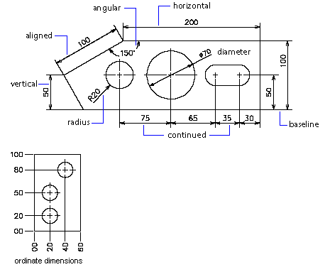
Angular and radial dimensioning are outside the scope of this
introductory course. Typically, users create a separate layer to hold
just dimension information. AutoCAD draws dimensions on the current
layer. Every dimension has a dimension style associated with it,
whether the default or the one you define. The style controls
characteristics such as colour, text style, and linetype scale.
Thickness information is not supported.
You use the DIM command to access dimensioning mode.
|
| Parts of a Dimension |
Refer to the figure below.
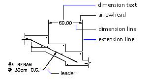
- A dimension line is a line that indicates the
direction and extent of a dimension. For angular dimensioning, the
dimension line is an arc.
- Extension lines, also called projection lines or witness
lines, extend from the feature being dimensioned to the dimension line
itself.
- Arrowheads are added to each end of the dimension line.
- Dimension text is a text string that usually indicates the
actual measurement.
- A leader is a solid line leading from some annotation to
the referenced feature.
|
| Linear Dimensions |
Linear dimensions can be:
- horizontal,
- vertical,
- aligned – with the dimension line parallel to the line along which
the extension line origins lie., or
- rotated
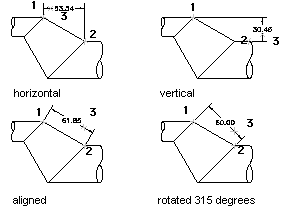
In all four illustrations, above, the extension line origins are
designated explicitly (1 & 2 respectively); the dimension line location
is shown at 3.
As you create linear dimensions, you can modify the text, the angle
of the text, or the angle of the dimension line. You can also place text
in any location using the User Defined option in the DDIM
Format dialog.
|
| (i)
Horizontal and Vertical Dimensions |
AutoCAD automatically applies a horizontal
or vertical dimension depending on the extension line origins you
specify or the point where you select an object. However, you can
override this as you create the dimension. As you create horizontal and
vertical dimensions, you can modify the dimension line angle as well as
the text content and angle.
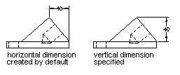
To create a horizontal or vertical dimension:
1. From the menubar, choose
Draw >
Dimensioning > Linear
OR
From the Dimensioning toolbar, choose
Dimensioning then Linear 
2. Press to select
the object to dimension, or specify the first and second extension line
origins.
3. Specify the dimension line location to
complete the dimension.
|
| (ii)
Aligned Dimensions |
In the figure below we see an example of
aligned dimensioning. The object is selected (1), and the location of
the aligned dimension is specified (2). The extension lines are drawn
automatically.
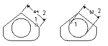
To create an aligned dimension:
1. From the menubar, choose
Draw >
Dimensioning > Aligned
OR
From the Dimensioning toolbar, choose Aligned Dimension 
2. Press to select
the object to dimension, or specify the first and second extension line
origins.
3. Edit the text content or angle.
4. Specify the dimension line location.
|
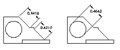
| (iii)
Rotated Dimensions |
Similarly to aligned dimensions, above,
i.e., use . Use appropriate option–i.e.
specify rotated option in command. See figure below for
examples.
|
| (iv)
Baseline & Continued Dimensions |
Baseline dimensions are multiple dimensions
measured from the same baseline (see figure below). Continued
dimensions are multiple dimensions placed end to end. There must
already be a linear, ordinate, or angular dimension before you create
baseline or continued dimensions.

To create a baseline linear dimension:
1. From the menubar, select
Draw >
Dimensioning > Baseline
OR
From the Dimensioning toolbar, choose Baseline Dimension 
AutoCAD uses the origin of the base dimension's first extension line
(1 in figure, above) and prompts for a second extension line origin.
2. Use Endpoint snap to select the end of the section (2, in
figure) as the second extension line origin, or press
to select any dimension as the base dimension.
3. Complete command.
The figure below shows an example of continued dimensions.
To create a continued dimension:
1. From the menubar, select
Draw >
Dimensioning > Continue
OR
From the Dimensioning toolbar, choose Continue Dimension
2. Use Endpoint snap to select the end of the existing
dimension as the first extension line origin.
3. Complete command.
|
| Editing Dimensions |
Dimensions can be edited with the AutoCAD edit commands
and grip editing modes. Dimensions may be stretched, trimmed, extended,
made oblique, or have their text edited. |
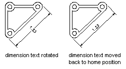
| Editing Dimension Text |
Once you've created a dimension, you can rotate
the existing text or replace it with new text. You can move
the text to a new location or back to its home position, which is the
position defined by the current style. Note that in the figure below,
the home position is above and centred horizontally on the dimension
line.
To rotate dimension text:
1. Go to the menubar and choose
Draw >
Dimensioning > Align Text > Rotate
OR
Go to the Dimensioning toolbar, click on the Align
Dimension Text flyout, and choose Rotate
OR
At the command line, enter DIMEDIT
2. Enter the new angle for the text.
3. Select the dimensions to edit.
|
|
Temple Exercise (cont'd)
|
| Resuming Session |
Log in, invoke Autocad and open your file saved after
completing the previous exercise. On entering the open command,
the Open Drawing Dialog Box will display files on your directory.
You can open your file by clicking, first on the file name and then on
OK.
If your file from last week is incomplete or requires corrections, do
this work first. Then qsave.
Now make a renamed copy (call it temple2.dwg; save it on your
Z drive) using saveas. Keep Ortho ON, restricting
movements to vertical and horizontal. (Use F4 key)
Creating a layer:
The next important step will be to dimension your drawing. At present
the drawing does not have a layer for dimensions. Making and setting
layers can be achieved with either the layer or ddlmodes
commands. The example shows the layer command.
Command: layer (or ddlmodes)
The Layer & Linetype Properties dialog appears. Click New.
Enter dim to name the new layer. Click on dim. Click on
the colour square to bring up the Colour dialog—choose a colour
for yopur dimensions. Click OK to return to the Layer.. dialog.
Click on Current button to make the new layer current. Click
OK.
Earlier tutorials show method of changing current layer if you are
not sure how to go about it.
|
| Drawing Scale |
CAD "drawings" are models of the objects they represent
and, until printed, are all full size (i.e., no scaling!). The
intended printed scale is still important, as it has a bearing on the
sizes of dimensions and text. While a drawing may display large or small
notes for purely graphic reasons, notes on architectural drawings are
typically proportional to the drawing scale. Titles that are appropriate
in scale to a 1:20 detail, for example, would be practically invisible
on a 1:200 drawing. AutoCAD includes commands that enable the user to
specify the scale and a great many other variables that govern the
behaviour and appearance of text and dimensions. Some AutoCAD add-on
packages like drcAuto provide facilities to facilitate the selection of
text and dimension settings and styles and drawing scaling. In this
tutorial the original prototype drawing used in the first tutorial (base.dwg)
was set up for a 1:100 scale drawing.
|
| Adding Dimensions |
AutoCAD's extensive dimensioning variables and commands,
can be invoked by selection from the menubar. Dimension commands ask the
user to define what is to be dimensioned and, with that definition, draw
the dimension lines, compute the dimension and display the text.
The menubar commands require selection by, holding down the Menu
(right) button, dragging the pointer across additional sub-menus and
releasing the button when the final option is reached.
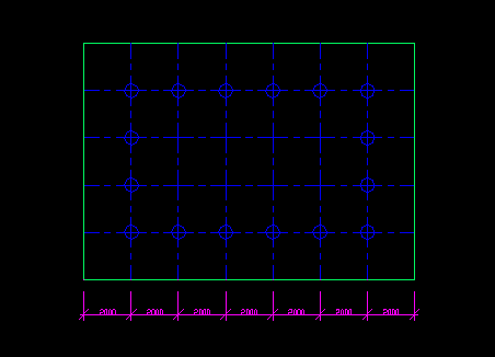
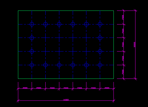
Dimensioning the first bay:
Command: Select from menubar
Dimension >
Linear
First extension line origin...: end
of
Pick bottom left corner of floor plan
Second extension line origin: end
of
Pick bottom of first grid line
Dimension line location:
Dimension line location...:
Pick location about 1000 below bottom line of plan
Dimension text = 2000 (AutoCAD will compute value)
Dimensioning successive bays:
Command: Select from menubar
Dimension >
Continue
Selecting Continue allows a quicker procedure to operate
Specify a second extension line origin...: end
of
Pick bottom of next grid line
Second ext..: end of
Pick bottom of next grid line.
Repeat, the above process until all bays are dimensioned (see figuire,
below).
Specify a second extension line origin...:
(to end)
Dimensioning Overall Building:
Command: Select from menubar
Dimensioning >
Linear
Then provide an overall dimension for the length of the building,
about 1000 below the grid dimension line you have just drawn. Use
end of snap, as above. See figure below. Select the bottom left
and right corners of the floor.
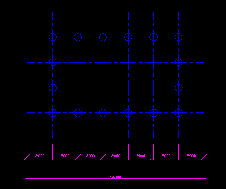
Command: qsave (save your work)
Vertical Dimensions:
Using the figure below as a guide, add the other dimensions shown on
that drawing.
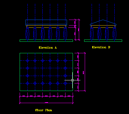
The procedure for drawing vertical dimensions is the same as that
used to draw horizontal dimensions.
Command: Select from menubar
Dimensioning >
Linear

Vertical dimensions may be generated using a similar sequence of
commands to that used for horizontal dimensions. You should work up the
page, to provide text the right way up if read from the right hand side
of the drawing. Dimensions that are wrongly positioned by AutoCAD may be
re-edited with the dimtedit sub-command. It is easiest to use
with Ortho set to OFF (Use F4 key):
Command: dimtedit
Select dimension: Pick dimension text to edit
Enter text location: Click at required location
Command: qsave (save your work frequently)
You may need to move the Floor Plan title when you place your drawing
border later in this tute.
|
| Adding Text |
The following instructions demonstrate how text of a
particular font and style can be incorporated into a drawing, with the
aid of the Textstyle Dialog Box.
Command: Change layer to text
Refer to earlier tutorials for method of changing layers.
Select from menubar
Draw >
Text >
Single Line Text
Text Justify/Style...: s
Style name (or ?): ?
Text style (*): *
Select a suitable style from the many displayed. (eg. Style 2)
Justify/Style...: s
Style name (or ?): style2
Justify/Angle/:
Pick start point below the the previously drawn dimension lines and
centred beneath the plan.
Height: 500
Rotation Angle<0>:
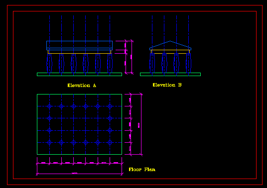
Text: Floor Plan
Move cursor vertically, up to a suitable distance below the long
elevation, pick a point and continue:
Text: Elevation A
Move cursor horizontally, across to a suitable distance below the
other elevation and continue:
Text: Elevation B
Text: (to exit)
Command: qsave (save your work)
|
| Completing the drawing |
Titles:
To complete a drawing it is only necessary to add drawing titles,
identifying the creator, the subject and title of the
drawing, date and scale. A professional office would
also include other essential information such as drawing number, north
point and perhaps a space to enter amendment details. Change the current
layer to then enter title text.
You may find it is a good idea to draw the borders, as described
below, before you add the drawing titles.
Borders:
Ready made borders are often stored as blocks, in libraries. For this
project it is suggested that you draw a rectangular polyline border
(Command: pline), with as the current layer, with the
bottom left hand corner at -5000,-5000.
Dimensions of the polyline outer border to fit a 1:100 A3 page, are
42200w x 29700h. The procedure would be to ensure ORTHO is ON and then:
Command:pline
From point: -5000, -5000
Arc/Close...: @29700<90
Arc/Close...: @42200<0
Arc/Close...: @29700<270
Arc/Close...: c (for close)
Refer to the figure below.
The inner border can be generated by offsetting (Command: offset)
the outer border, by 1000. (ie. 10mm at 1:100)
Minor repositioning of the border can be achieved, if necessary, by
using the move command.
Don't forget to include the drawing titles if you haven't already
done so.
Command: qsave (save your work)
|
Modelspace and Paperspace
|
| |
AutoCAD has two main graphic display modes:
- TILEMODE ON (or 1). This is the mode you have used so far. In this
mode it is possible to create additional tiled or mutually
exclusive viewports, to split the screen like tiles.
- TILEMODE OFF (or 0), also referred to as floating or
paperspace mode. In this mode you must create all viewports, but
these viewports are floating, in the sense that any viewport
can be overlaid on another, so that you can produce more interesting
graphic arrangements.
|
| Modelspace |
Up to this point, you have worked in modelspace.
Modelspace is 3- dimensional space. You can change your angle to
the model and see it as a 3-dimensional object. Modelspace is the
drawing environment that exists within any viewport. |
| Paperspace |
Paperspace is a 2-dimensional environment for
arranging views of your model for display or plotting.
Think of paperspace as an infinitely large sheet of paper on which
you can arrange viewports that show your model.
As its name implies, paperspace represents the paper on which you
are going to print your drawing.
NOTE: You do not have to be in paperspace in order to plot, but for
the commands we are about to use you will transfer between TILEMODE ON
and TILEMODE OFF in order to perform certain tasks.
Now, change to paperspace (TILEMODE OFF) by double-clicking
the mouse arrow on the button (at the bottom of the AutoCAD window)
labeled TILE (see figure below).

|
| |
If you have completed this task, the button beside it
will now be labeled PAPER (see figure below)

and the word TILE on the TILE button has become "dim" or grey. This
indicates that you are no longer in TILEMODE.
Do not be alarmed that your drawing suddenly disappeared when you
change to PAPER SPACE. It is now being covered by a virtual "piece of
paper." All "TILED" Viewports that you may have set through the VPORT
Command will disappear
while you are in this mode. You can return to TILEMODE when necessary by
double-clicking the same button.
|
| |
|
|
 |
You know you are in paperspace by the icon in the
lower left corner of the graphics window. The familiar UCS icon has been
replaced by the one shown in the adjacent figure.
Think of paperspace as an opaque sheet of paper held in front
of your model. You can't see the model because the paper blocks your
view unless you cut openings in the paper to look through. Suppose that
instead of just clipping "peep holes," you could also mount a monitor in
each of the openings you cut, and each monitor is connected to a TV
Camera. Each TV camera transmits an image of the model to its monitor,
but each camera does not have to be positioned the same relative to the
model. With each camera in a different position, each monitor would
display a different view of the model. In AutoCAD, changing the camera
position is accomplished by the Viewpoint (VPOINT) Command you
used earlier—look for the tiled vports exercise in the tutorial
exercise.
For the purposes of creating multiview projections, the views you
want to project to the "port monitors" are those you are already know
(FRONT, TOP, and RIGHT SIDE). Let's talk about how this relates to
paperspace. In paperspace, you create "floating" Viewports
instead of tiled Viewports. This is why you are no longer in TILEMODE or
TILEMODE is OFF or 0. In other words, the viewports you create are not
automatically arranged in a distinct grid pattern.
Floating viewports can be any size, at any position, can overlap,
and can be moved around. They also can display a STATIC "snap shot"
view of the model, or a DYNAMIC "editable" view of the model. These are
the two modes you can use when TILEMODE is OFF or 0. In the "static"
mode of paperspace, like a snap shot or photograph, you cannot edit the
Paper image because it is frozen; however, you can add 2D elements such
as centre lines and dimensions, like drawing on a photograph. These
elements are NOT part of the photograph, but are on the surface. So
think of adding elements to a drawing in the "static" mode of paper
space as drawing on a transparency placed over the views. In the
"dynamic" mode of paperspace the viewports display the model again and
the model can be edited in any viewport. Look at the three figures below
which show the STATUS BAR located at the bottom of the AutoCAD Window.
These figures show the look of the last two buttons on the status bar
when certain modes are active.

TILEMODE =1
With TILEMODE set at 1, you are looking at the MODEL, and you can
setup TILED VIEWPORTS. When TILEMODE=1 you are only see the MODEL. When
TILEMODE is set to 1 the word TILE is dark (known as highlighted).
TILEMODE=0
With TILEMODE set at 0, you are in PAPER SPACE and the TILE
button is dim (or gray). With the word PAPER showing you are in the
"Static" side of paperspace, and to see the model you must create
floating Viewports through which you can view the model, but the model
is like a photograph (or frozen in place) and cannot be edited.
To change to paperspace, double click on the word MODEL or TILE. The
word PAPER will appear.

TILEMODE=0
With TILEMODE set at 0 (the TILE button is dim, and the word MODEL
showing in place of the word PAPER, you are now in the "dynamic" side
of paperspace and the floating viewports display views of the model
which can be edited. The second button from the right is a toggle
between the Paper and Model side of paperspace. To change to the Model
side of paperspace, double click on the word PAPER, but the TILE button
must be dim. To change back to the "static" or Paper side of Paper Space
double click on the word MODEL. Double click on the TILE button and see
that you return to the original view of the model you just had. The
MODEL button (next to TILE) also reappeared. Double click on the TILE
button again, and you will be back in the "static" side of paperspace;
however, you cannot see the MODEL, because you have not created floating
viewports through which to see it. |
| |
|
Plotting
|
| |
Before starting to plot you should zoom out so
that all of your drawing or image is contained within the screen, with
some free space around it to make selection easy.
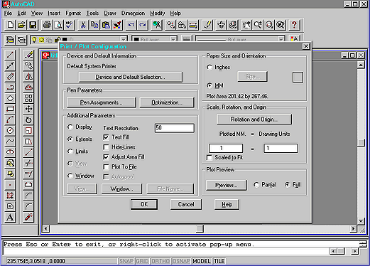
Now, to plot the drawing:
From the pull-down menu, click File => Print
or
At the Command: prompt type plot,and
on the main screen, the Print / Plot Configuration dialogue box
will appear).
When the box appears make sure that these items are selected:
-Under the heading Paper size and Orientation click
on mm and A size paper.
-Click on the Rotation and Origin bar. Type
0.000 by x and0.000 by y if not
already there.
-While in Rotation and Origin change the orientation
to90degrees.
-Look at the box marked to Scale to Fit, and if a check
appears in the box, click on it to deselect.
-Under Plotted MM=Drawing Units type 1=1
-Under Additional Parameters click on Extents.
-Click on the button marked Pen Assignments. When a dialog
box appears, click on the row labeled 7 (for white), and then
move to the Width window and change the size to .7.
| Before moving on, check
these settings again. Changing some settings before others will
change settings you have already made and your print will have
errors.** |
-Click the Full button, then click the Preview Bar to
examine the way your file will plot.
**To EXIT Print Preview**- Click the RIGHT
mouse button on the screen and a dialogue box will appear. Drag down
to EXIT and you will return to the Plot Dialogue box.
-If everything looks OK, then click the OK button and the
print will be sent to the printer.
|
At
the Finish
|
| |
That's all for now. Save your drawing (if you haven't
already) and then exit AutoCAD:
Command: end (to save and exit)
Remember to log off before leaving. |
|